How To Create Alignment In Civil 3d
- Get It
$19.99
$19.99Civil 3D Essentials Book and Practice Files
Civil 3D Alignment from objects: A step by step tutorial guide
Introduction to Civil 3D Alignment from objects
Firstly, what is a Civil 3D Alignment from objects ? Well, let's find out in this online training course. Certainly, this step by step tutorial is a part of the Civil 3D essentials book and how-to manuals . Beside Objects, what other Civil 3D Alignment do we have?
Alignments allow us to represent or design linear objects such as roads, sidewalks, railway tracks or survey baselines.
They are also useful for the creation of design items such as profiles, road corridors, cross-sections, or earthworks volumes.
Alignment objects are typically composed of lines, curves, spirals or a combination of these elements. They can be created from an already existing entity (mostly lines, arcs or polylines) or by using the Civil 3D Alignment Layout tools .
This chapter kicks off the process of the detailed design of the subdivision. Processing the survey data, creating alignments and laying out parcels sets up the table for the ensuing design. The process of designing a subdivision street will include, among other components:
- The creation of Alignments. They provide the two-dimensional information needed to determine the path that the road will take.
- The design of Profiles. They give us the 3rd dimension, the elevation information at each point along the alignment.
- And, the design of a Typical Cross-section. It tells us the different sub-entities, such as pavement, sidewalks, and curbs, that compose the road.
Now suppose that the project is located in the municipality of Flower Bay . We must then design the road following the local standards as required for a 14m or 46ft local road right-of-way. That includes, on both sides,
- A 7m or 25ft road travel way or pavement.
- A 20cm or 6in curb.
- A 1.5m or 5ft sidewalk.
- A 1.8m or 6ft green space.
In Civil 3D, we have two main ways to create an alignment: From existing objects (lines and polyline) or by layout (using the Alignment Creation tools) . Creating civil 3D components from an object or by creation tools is a recurring theme. As we have done for surfaces, we will use these two methods for alignments, profiles, pipe networks, and feature lines.
Creating a Civil 3D Alignment from objects?
Let's get started with creating alignments from objects.
- Open the 07.01-Alignments dwg file in Lesson 07 practice folder.
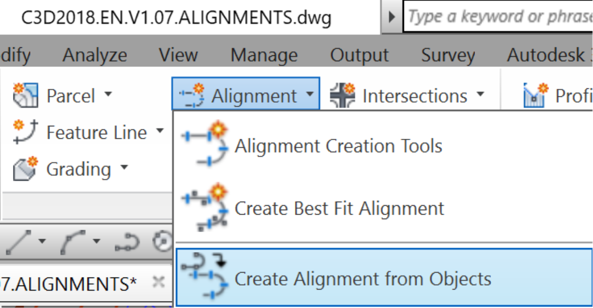
- From the Ribbon, select Create an alignment from objects.
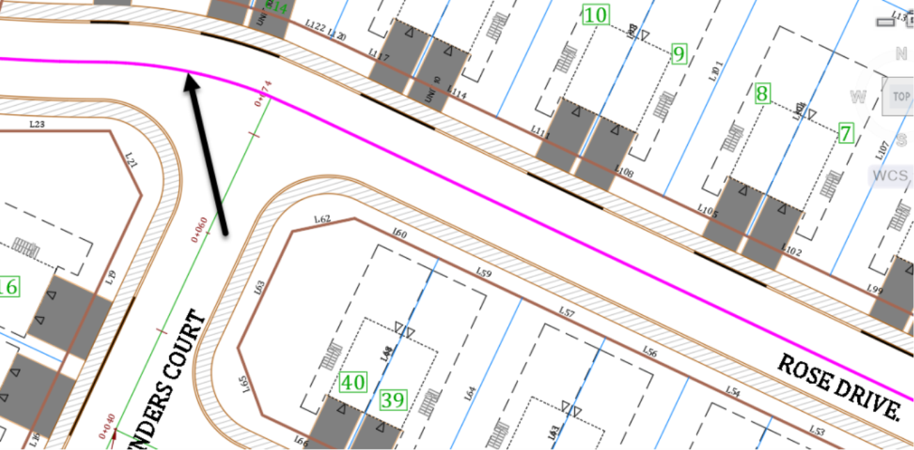
- Select the magenta polyline object at the centerline of Rose Drive. The main site access road and the baseline were already established during Phase 1 of the project. Click towards the western end of the polyline so that the orientation of alignments stations is from West to East. It is always recommended to have alignments run West to East and South to North, to make plans and profiles more readable in layouts.
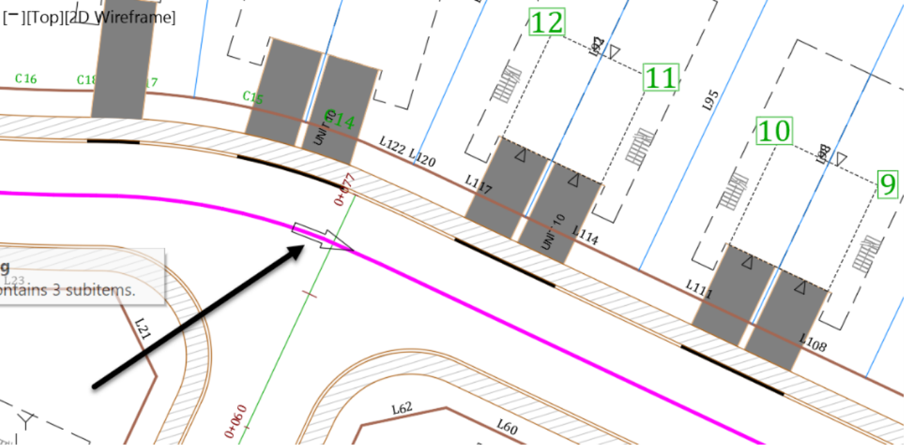
Afterward, press Enter at the command line twice. The second time would be to accept the alignment direction. If you missed it or have the alignment in the wrong direction, don't worry and keep working. We will be able to change the direction of the alignment.
- Next, in the create alignment from Objects window,
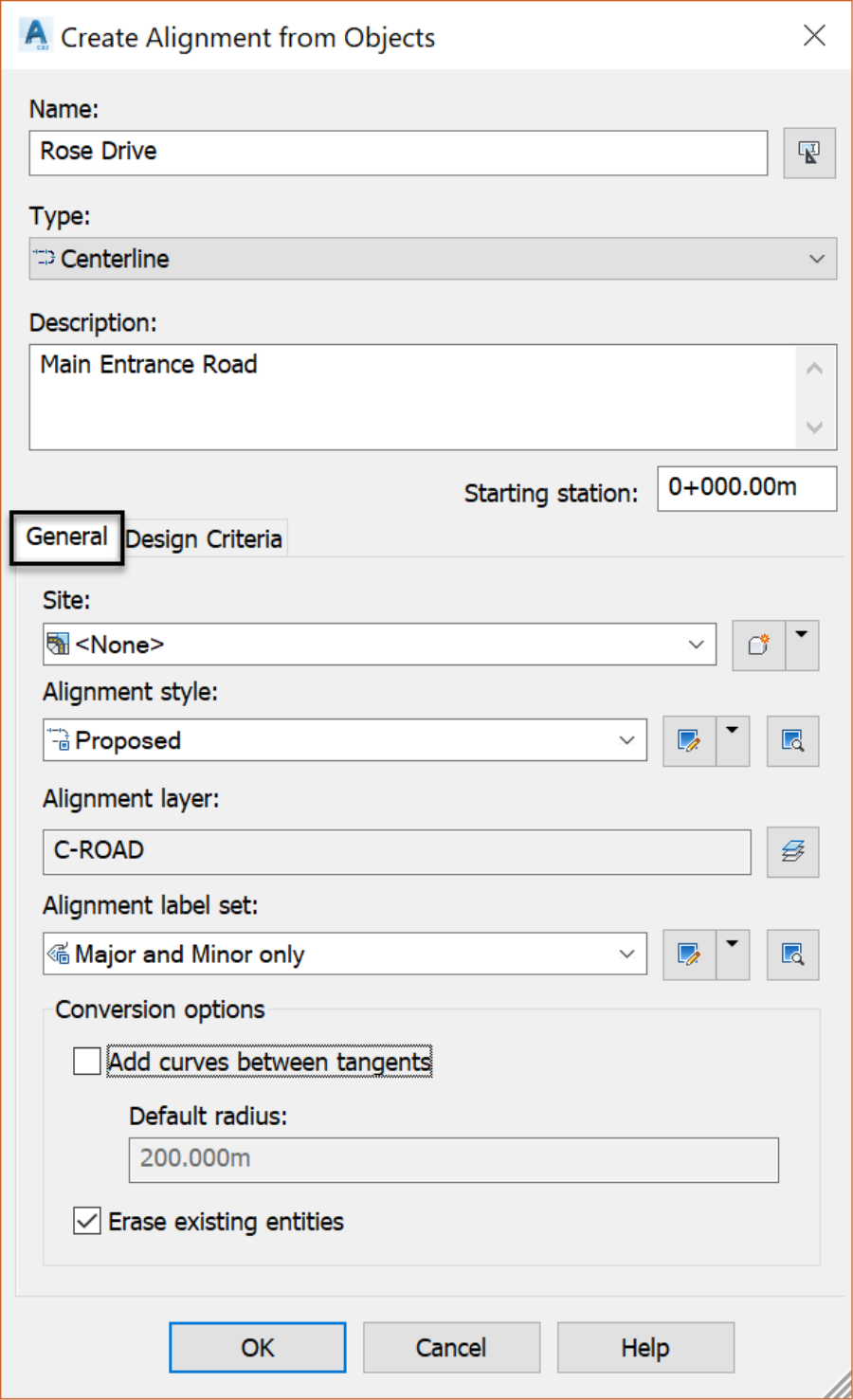
- Name the alignment Rose Drive.
- Then, choose a Centerline alignment type. Alignments can be either of type centerline, offset, curb return, rail, or miscellaneous. Alignments are categorized based on their function. You can use centerline types for a road centerline, the rail type for a railway, or the miscellaneous type for other uses, such as a utility conduit. Also note that after creating the alignment, you can change it by using the alignment properties window.
- Do not specify a site as we are not looking to have any interaction with other items.
- After that, use the major and minor label set, to display tick marks at minor stations and values at major stations.
- Next, make sure to uncheck the Add Curves between the tangents checkbox. Use this option in situations where we want to create curves between adjacent lines. It is obvious that the curves are already created in our case when we first created the baseline. Consequently, we don't need to create any more curves.
- Finally, check the erase of the existing entities' checkbox to erase the original polylines. Once you create the alignment, the polyline is not needed anymore and can be disregarded. If for any reason we need it, we can simply offset the alignment to recreate it.
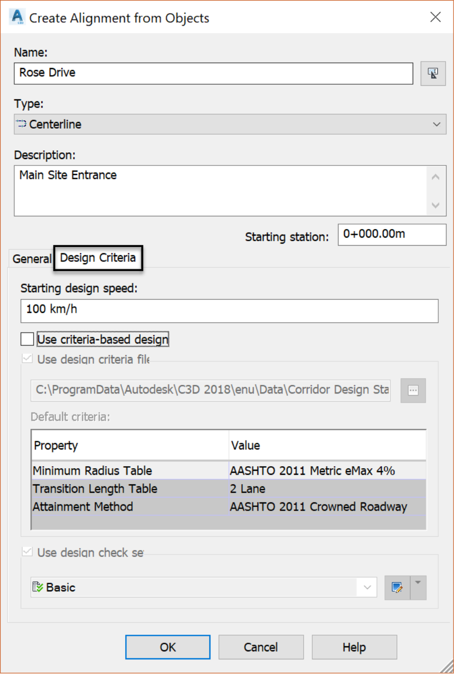
- Now, switch to the Design Criteria tab. First, we can specify a Design Speed at the alignment starting station or other stations. This option is mostly used for the design of major roads when calculations such as super elevations are needed. To make these calculations, we can perform a Criteria-Based Design. We can use this method to meet a certain criterion when a standard file is supplied by a department of transportation. In this case, the default file is the Civil 3D Metric (2011) Roadway Design Standards XML file. To specify a design criteria file, click on the small button with the three dots
 . Then, you are directed to the default criteria folder where you can choose the criteria file you would like to apply. You can make a copy of any of these files, adjust them to your own local criteria requirements, by using a text editor and save it in this same folder.
 - Finally, you can specify a Design Check Set List to display design checks and receive messages when a design criterion is not met.
- Before closing this window, make sure the Use criteria-based design is unchecked.
- To finish, Click OK to create the Rose Drive alignment. It is then shown with stations showing every 20ms or 50ft , depending on the units of your practice drawing.
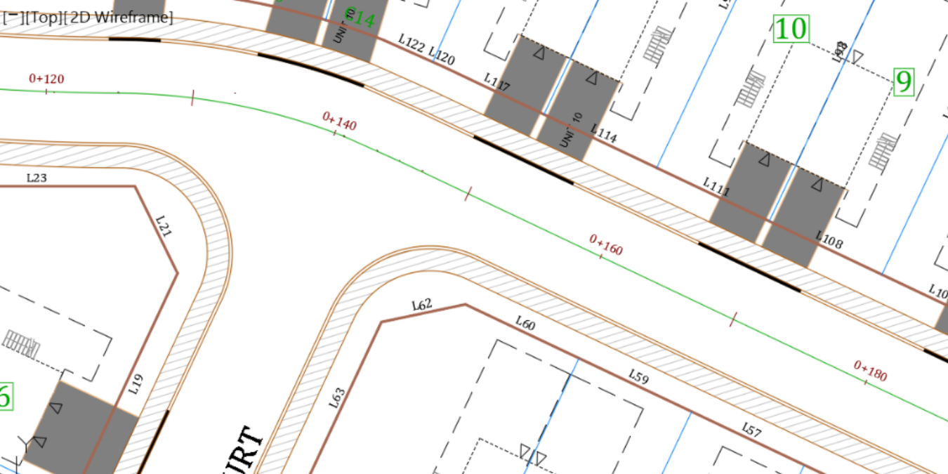
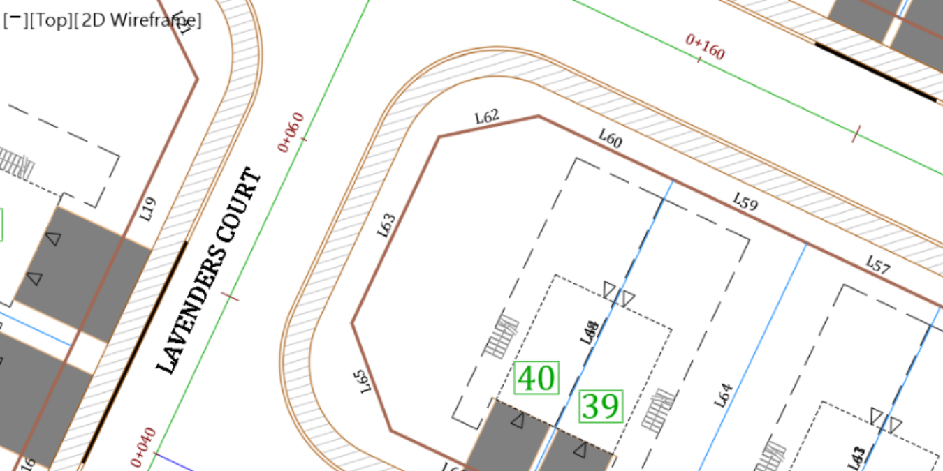
- Use the same previous steps to create an alignment for Lavender Court using the magenta line in the centerline. In the end, you should have an alignment running south to north, with stations showing every 20m or 50ft depending on your practice file units.
Related Civil 3D Training Courses and Books
- Get It
$19.00 / year
$19.00 / yearCivil 3D for Beginners: Level 1
- Buy Now
$79.00 / year
$79.00 / yearCivil 3D Essentials
How To Create Alignment In Civil 3d
Source: https://www.infratechcivil.com/pages/civil-3d-alignment-from-objects
Posted by: healeywimen1958.blogspot.com

0 Response to "How To Create Alignment In Civil 3d"
Post a Comment